Before turning on the soldering iron, take the sponge from underneath it and red it down so you can use it to clean the tip of the soldering iron and open a window to let out some of the fumes.
After you are done soldering, if there is no one directly in line behind you, turn of the soldering iron
Current and Power
Setting up a multimeter: Before using the multimeter to measure current, you have to make sure to reconnect the red wire to the input with the “A” above it (lower left side)
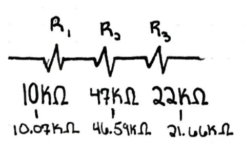
Lowest Resistance Resistor:
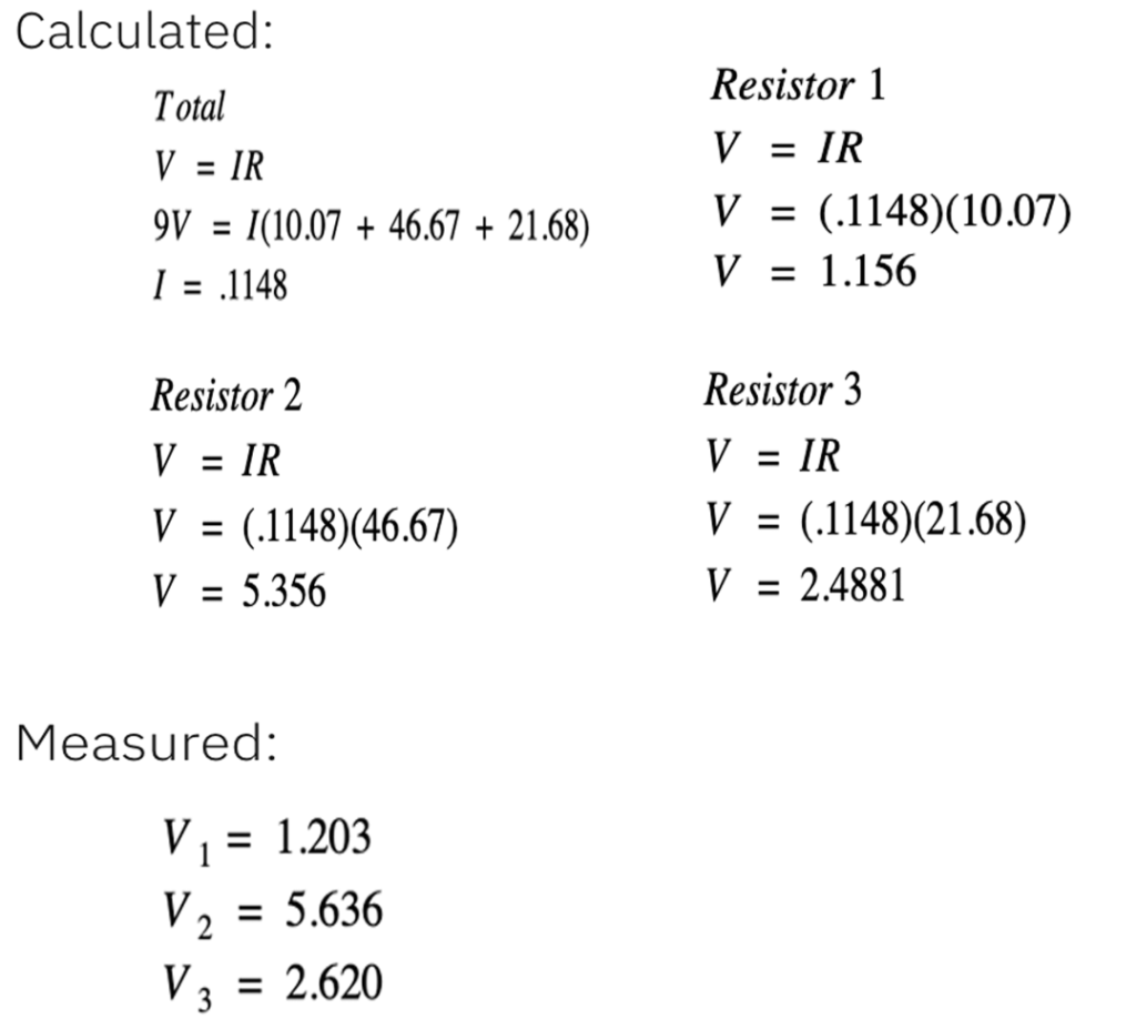
Measured:
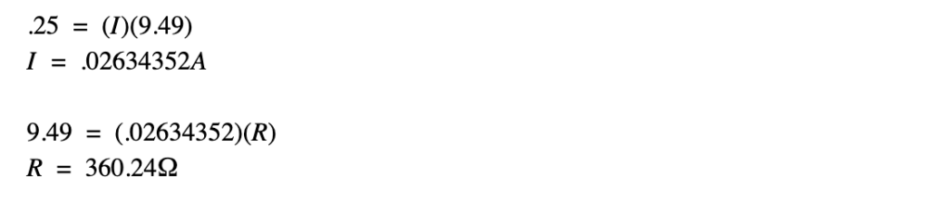
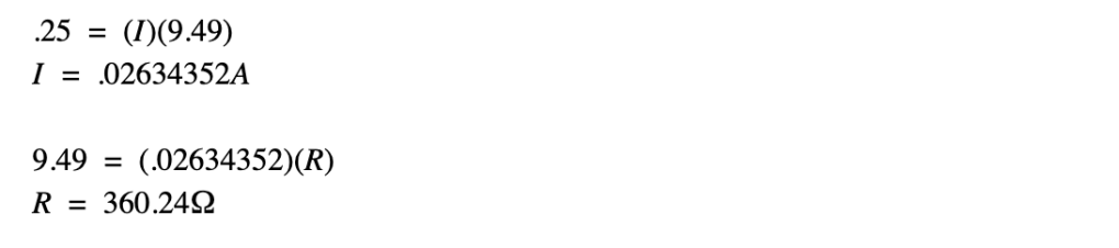
Calculated: Current measured at .20 amps when using a 470Ω resistor
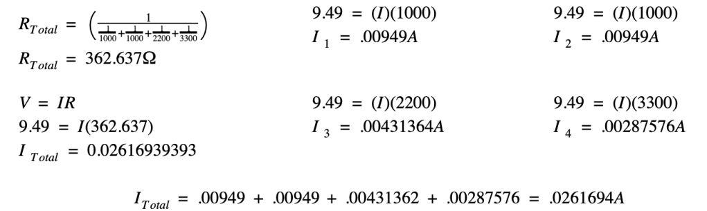
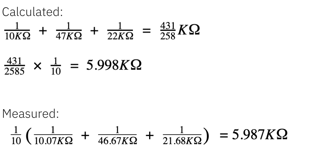
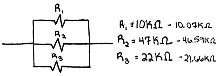
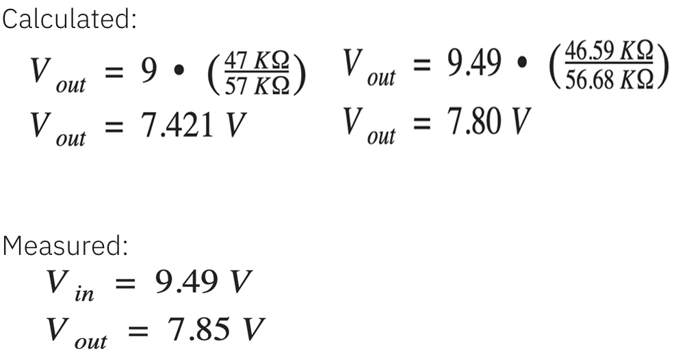
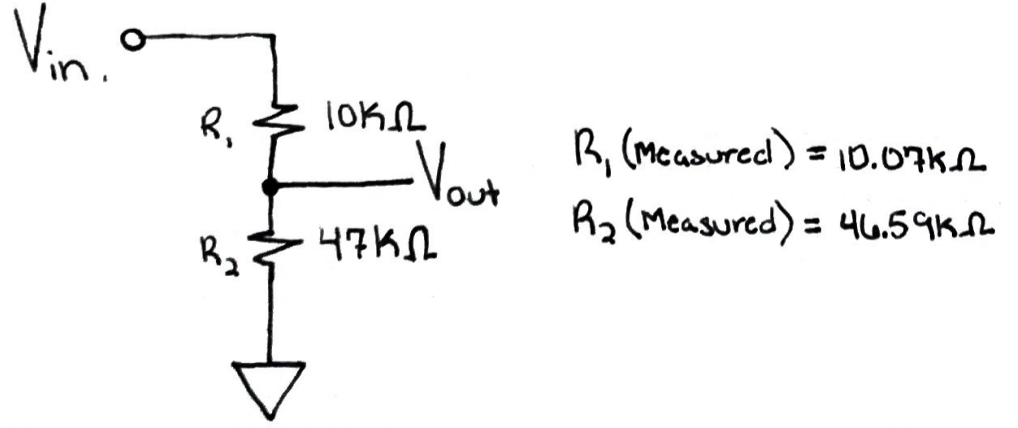
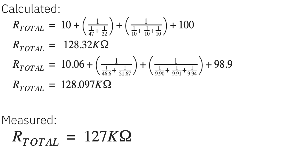
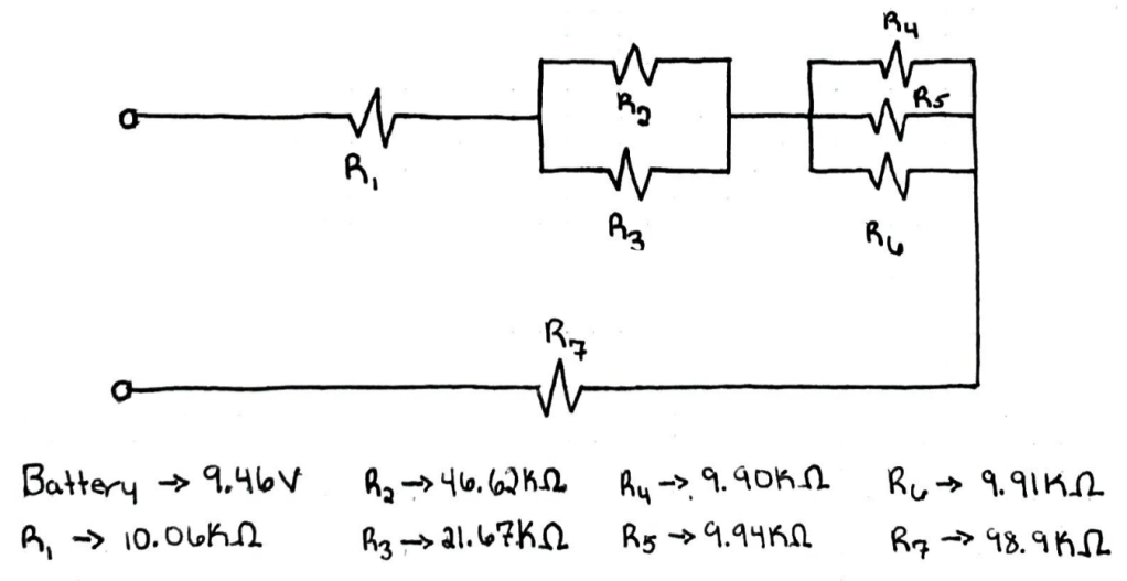
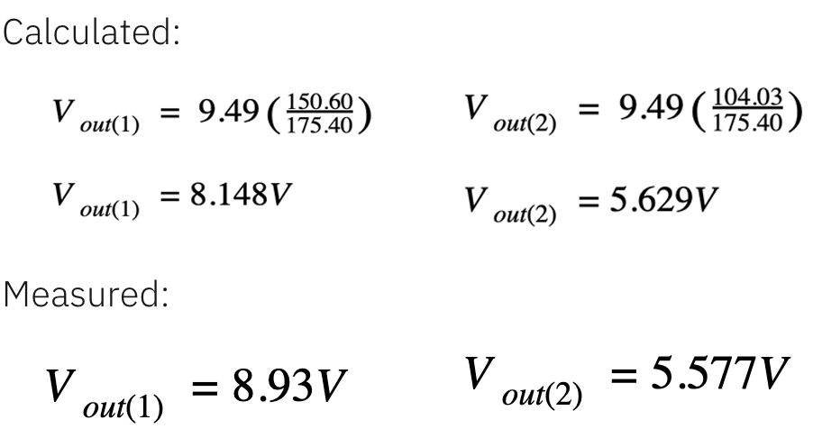
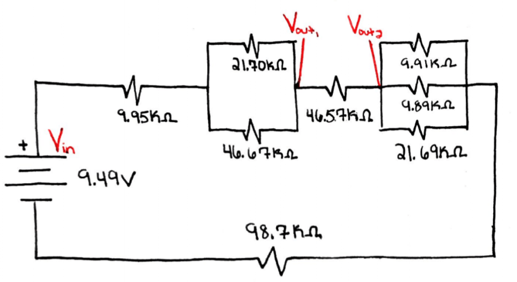
Before doing the calculations for the Voltages, the total resistance between Vin and Vout(1), Vin and Vout(2), Vout(1) and ground, and Vout(2) and ground were calculated using the equations for resistors in parallel and series.
When looking at a breadboard you will see it almost looks as if it is divided into different sections. The two outside panels have power and ground columns and the two inside panels connect different components of your circuit together. The red line on the outer panels indicates that the column of holes alongside it is power and the blue line indicates that the column of holes ground the circuit. When connecting components in the breadboard, the rows on the inside panels are all connected. Each row of five will connect anything else in that row, however, this row doesn’t continue over the break in the center. Each side of the break is its own system of rows and columns.
It is crucial to know these elements of the breadboard so when creating your circuits, you can trace the path of the current from your DC power source (in this case, a 9V battery) through your components and eventually to ground. To connect your power source, you will use a red wire to connect to power and a black wire to connect to ground. Once this is done, you will be able to have power in your circuit. To be safe, disconnect your power as you build your circuit so you can avoid any unwanted short circuits.
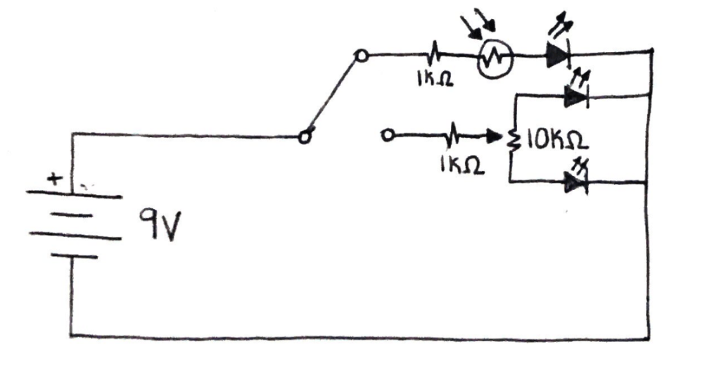
Schematic (two resistors)
Schematic for a circuit that uses a switch to change between an LED light with a photocell to control brightness and a potentiometer that cross fades two LED lights
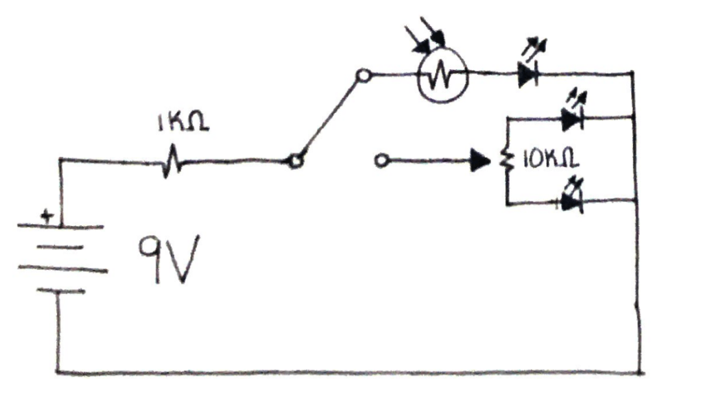
Schematic (one resistor)
Schematic for a circuit that uses a switch to change between an LED light with a photocell to control brightness and a potentiometer that cross fades two LED lights
A multimeter can be used to measure the electrical values such as voltage, current, and resistance. The multimeter consists of a body where you can adjust settings and chose what you are measuring and two wires with metal probes on the ends (red and black wires). Measurements can be completed by placing the two metal probes on either end of the area you want to measure. The red wired probe should be on the side where the power is coming into the segment and the black wired probe should be on the side towards ground. There must be two points of contact otherwise there won’t be a reading.
Multimeters are a useful way to troubleshoot circuits because you can measure multiple different things to find the true problem. A multimeter can be used to check to see how much voltage is in a battery as most batteries won’t have their exact voltage. For example, when a 9V battery was tested during lab, the voltage shown was 9.6V instead of 9.0V. They can also be used to find any components that aren’t working properly (such as a short circuit) so they can be replaced. You can also make sure current is running through the whole circuit.
Looking Back At Past Final Projects
The first project I looked at was Jillian Olsen’s reverb pedal. It was really interesting to see how she used the spring and extra parts to create this. By placing her breadboard inside the box so you could only see the knobs, she created an organized look to the pedal. I liked how she added the high pass filter as well as the gain and dry/wet settings to allow the user to do more with the sound.
I also looked at Jake Sandakly’s synth clarinet. I was fascinated with this project and how he used the microphone to act as a mouthpiece. It was interesting to see how he connected the oscillator to different resistors to create the notes. Jake’s project was intricate and though I didn’t understand everything, it was still interesting to watch his video and read about how he made the synth.
The final project I viewed was Jaye Sosa’s polyphonic synthesizer with adjustable tremolo. I liked how she used the LED light to give a visual representation of the tremolo as it was adjusted. It was interesting to read about her use of the DPDT to connect the two oscillators to trigger them at the same time. I enjoyed reading about how her project worked and then going back and watching her videos again once I knew more about the project.