Analog Lab Week 13

April 27, 2020

Digital Projects

I looked at Crystal’s Laser Beam Ukulele, Lauren’s Capacitive-Touch Painting, and Paul’s Grain Cube. I chose these projects because they were designs that I had never seen before. I really enjoyed the Laser Beam Ukulele because I play guitar and ukulele and it was interesting to hear how the design looked and sounded. The Capacitive-Touch Painting was incredible and it was really interesting to look at how she set up her circuits to work with the painting. I didn’t even know that existed until I watcher her video. I loved the idea of using the game cube controller to control the granular synthesizer. I enjoyed looking at the code for all of the projects and learning how they came to their final results.

Arduino Projects

Arduino Organ With Kinder Surprise

I love the concept of using your own body’s electrical capacitance as part of a project. The circuit included wiring kinder eggs so when you touched them, there was sound. This can be done with any foil but it was definitely more interesting to see kinder eggs wired into a circuit.

Touchless Doorbell

I found a lot of projects that involved social distancing and thermometers but I found this one more unique than the others. It was interesting to see how the sensor (that id seen used in audio projects as well) could be used so that people aren’t spreading the virus. An IR Sensor Module was used to detect if an object was in front of the sensor and output “HIGH” if there was an “LOW” if there was nothing there. This then translated into code to trigger a doorbell or not.

Analog vs Digital Inputs

In digital electronics terms a switch or button is a digital input, an LED is a digital output, and a potentiometer is a analog input.

Computer Programming Experience

Yes, I’ve taken introduction to computer programming (Python) and introduction to computer science (Java) at NYU. I’ve also taken a high school AP Computer science that was Java but it was all through code.org.
Analog Lab Week 12

April 20, 2020

Intro to 555 Timers

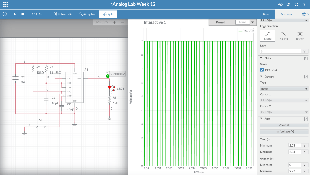
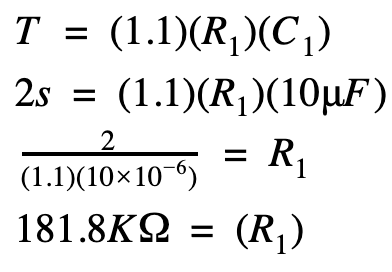
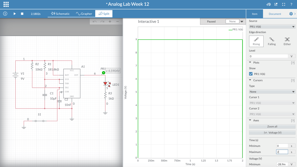
1. Using Multisim, build a Monostable Multivibrator that has a decay of around 2 seconds. Determine the value of R1 assuming you are using 10uF for C1. Take a screenshot of the split screen showing that the pulse stays “high” for about 2 seconds. Also include a link to your Multisim page.

The pulse stays “high” for about two seconds but after that it starts going high and low very fast. I am working to figure out why it does this but I haven’t gotten it yet.

The 555 Timer Circuit – – – My Page

2. Find an example of another project that is based on a 555 Timer. What is the chip being used for? Can you identify if it is an Astable, Monostable, or Bistable multivibrator? Or none of the above?

The chip is being used to create a voltage controlled oscillator. It is an astable multivibrator.

Project: https://www.multisim.com/content/p8ftihA3q27xTTBJgzU6XM/555-timer-voltage-controlled-oscillator/

Analog Lab Week 11

April 13, 2020

Guitar Pedals

1) Research at least 3 different analog guitar pedal manufacturers. Here is a huge list if you need it. Try to look at big brands who manufacture a lot of pedals as well as boutique companies that have smaller lines.

I looked at:

1a) What do you like and dislike about them? What types of pedals do you find interesting, and that you wish you could learn more about? Try to pick out analog effects and not digital ones.

I found that what first drew me to a pedal was the style of it and the appearance (boutique shop pedals especially). I was drawn in by the style and then I would explore what the pedals did. I picked out a bunch of pedals that happened to be fuzz/drive pedals. It was interesting how the different companies set up the pedal and how it functioned (what types of switches/pots were used). Id like to learn more about how some pedals transitioned from analog to digital and how effects could be done in both but might be easier digitally (differences between creating an analog reverb with a spring and a digital reverb).

1b) Can you describe any overall differences in approach that you see in what bigger companies (Boss, MXR, Ibanez, TC Electronics) are making, and what smaller “boutique” companies (for example – Death By AudioZVexFairfield CircuitryWalrus AudioT-Rex) are making?

The big companies keep their outside pedal design simple. Most of the pedals are a single color with the needed switches and pots on the top of the pedal. The boutique pedals combine handmade circuits with a more unique outside that draws the buyer in. All of the boutique companies’ pedals that I was looking at are hand made wherever the company is based out of while bigger companies have larger separate factories to mass produce pedals. The boutique companies are manufacturing more specific or unique pedals (whether that is in what the actual pedal does or the design aspect of it) instead of a one size fits all design and “generic” effect.

1c) The possibilities for guitar pedals and analog effects are literally endless. See if you can find a pedal that has a sound, controls, or features that are undeniably different from anything else. Post a link, photo, or video demo of it and explain what’s unique about it.

Design wise, the Dr. No Effects Skull Fuzz Original is unlike any pedal I’ve ever seen. The function is the same as other fuzz pedals however the pedal is a skull instead of a “normal pedal” design. There is a latching button on the top to trigger the fuzz and the eyeballs function a volume knob and a knob to control the fuzz. There is also a switch on the side of the skull to vary the fuzz.

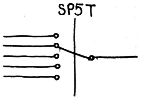
2) Draw a diagram for a SP5T switch. What kind of switch is this?

An SP5T switch has a single pole and 5 throws.

3) Explain the difference between a momentary button vs a latching button. What kind of application could you use each type for?

A momentary button engages the circuit when it is pressed down and disconnects when it is not pressed down. Momentary buttons are good for creating a scale with an oscillator and you use a bunch of different momentary keys so when you press one it only plays that note for as long as it’s pressed. When a latching button is pressed it clicks and it will engage the circuit until it is pressed again. Latching buttons are good for pedals when you want to engage the effect for a sustained period of time until you press the button again.

Analog Lab Week 9

March 30, 2020

Diodes / Diode Clipping Distortion

1) For this circuit…

Screen Shot 2020-03-27 at 6.49.41 PM.png

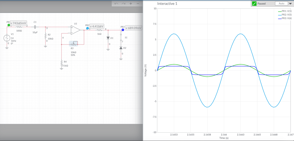
…if the sine wave you’re putting into the diode clipping circuit is loud enough to distort, which of these will the output signal look like? It will look like A

a)

Screen Shot 2020-03-27 at 6.42.00 PM.png

b)

Screen Shot 2020-03-27 at 6.41.15 PM.png

2) For this circuit…

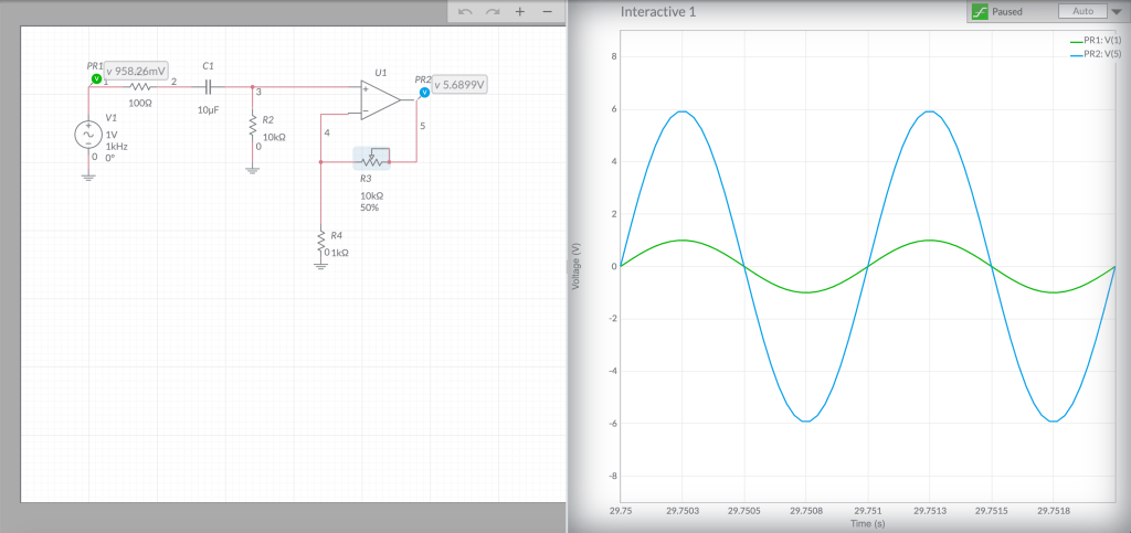
Screen Shot 2020-03-27 at 6.49.10 PM.png

…if the sine wave you’re putting into the diode clipping circuit is loud enough to distort, which of these will the output signal look like? It will look like B

a)

Screen Shot 2020-03-27 at 6.42.00 PM.png

b)

Screen Shot 2020-03-27 at 6.41.15 PM.png

3) Assume the speaker symbol is any pair of headphones or a small speaker, and you test both of these circuits with the same headphones or speaker. Is it safe to assume that the output of these two circuits will sound the same and be the same volume?

Yes because the op amp that is connected in the second circuit acts as a buffer so it has the same Vin and Vout causing there to be no audio/volume difference between circuit 1 and circuit 2.

Circuit #1:

Screen Shot 2020-03-27 at 7.00.03 PM.png

Circuit #2:

Screen Shot 2020-03-27 at 7.00.36 PM.png

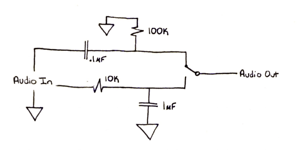
4) Below is the schematic for the circuit I made in the video. I’d refer the potentiometer at the end, right before the output circuit, as  the “crossfader”.  With this circuit, if you turn the crossfader all the way to one side you’ll hear clean signal.  If you turn the crossfader all the way to the other side you’ll hear distorted signal.

5) If you turn the potentiometer to its halfway point, you’ll hear both clean and distorted as its morphing between the two (the exact average of the voltages of the clean and distorted).

Screen Shot 2020-03-27 at 7.21.54 PM.png

Analog Lab Week 8

March 23, 2020

Oscillators

1) With the oscillator we’re studying the comparator outputs a square wave and the integrator outputs a triangle wave.

2) With an integrator, if Vin is positive the output voltage ramps down (up/down). If Vin is negative the output voltage ramps up (up/down).

Screen Shot 2020-03-23 at 10.22.06 AM

3) With a comparator, if the op amp’s + input is connected to a greater voltage that that connected to it’s – input, the op amp’s output will be about positive (positive/negative) 9v DC.  If the op amp’s + input is connected to a lower voltage that that connected to it’s – input, the op amp’s output will be about negative (positive/negative) 9v DC.

4) There’s a formula for how fast the integrator ramps up or down:

change in volts per second at Vout = -Vin / RC

So the bigger the resistance R you use the slower (faster/slower) the ramp gets, and the bigger the capacitor gets the slower (faster/slower) the ramp gets.

5) The circuit at the end of this video is a monophonic synthesizer – it can only output one tone at a time. What do you think would have to do to make a polyphonic synthesizer that could play 2 notes at the same time? 3 notes? 4 notes? 100 notes?

You could make two circuits that have the same output. So you have your right hand notes that you could play and your left hand notes. You would be able to play the right hand and left hand at the same time but not different notes at the same time in the same hand.
I don’t know how you would set it up keeping the circuit roughly the same as it is in the video because if you press two of the buttons at the same time, the current going through each potentiometer would be different because they are in parallel causing the tuning to be off.

Analog Lab Report 6

March 9, 2020

Adjustable RC Circuit Filters

10K Potentiometer:

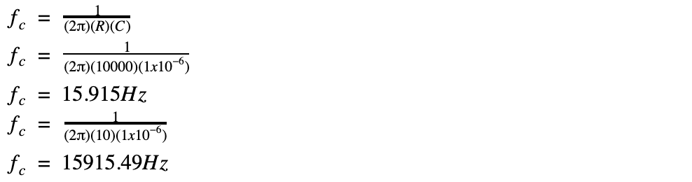
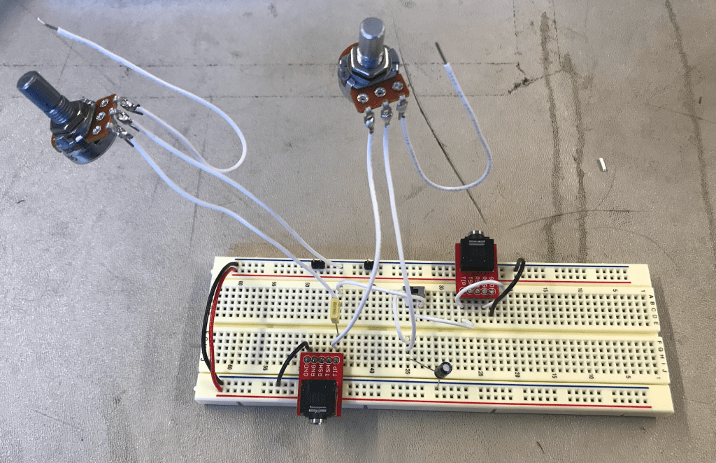
A 1 microFarad capacitor needs to be used for a 10k potentiometer in a high/low pass filter

100K Potentiometer:

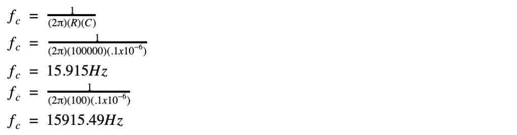
A .1 microFarad capacitor needs to be used for a 100k potentiometer in a high/low pass filter

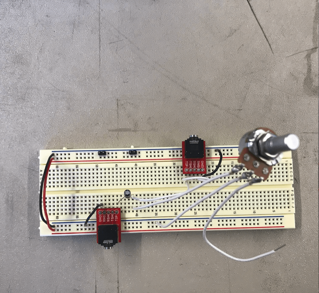
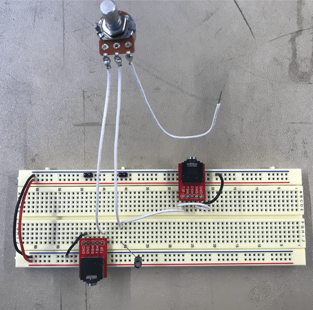
High Pass Filter:

Low Pass Filter:

Dual:

Filter Question:

To make a 12 dB/octave filter instead of 6 dB/octave filter, I would layer the same filter again to expand the range.

Start Contemplating Final Project:

I think it would be fun to build some sort of guitar pedal that I would be able to keep using after the class ends. I would like to do a spring reverb, gain, and maybe overdrive. I think it would be interesting to not only build this but also learn how pedals today work versus how we build things in class. I am also interested in synthesizers and being able to get specific tones to trigger when you hit certain buttons. And learning how store-bought synthesizers work (digital vs analog).

Troubleshooting:

Troubleshooting notes found HERE

Analog Lab Report 5

March 2, 2020

Make a bipolar power supply with two batteries

V(normal) = 9.36

V(with other ground row) = -9.63

DC blocking, current limiting circuit

Adding a resistor and a capacitor on each end allows the AC current to flow while blocking any DC current. If the DC current wasn’t blocked, it could damage expensive equipment such as laptops, speakers, and headphones.

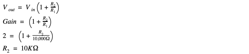
Non-inverting Amplifier

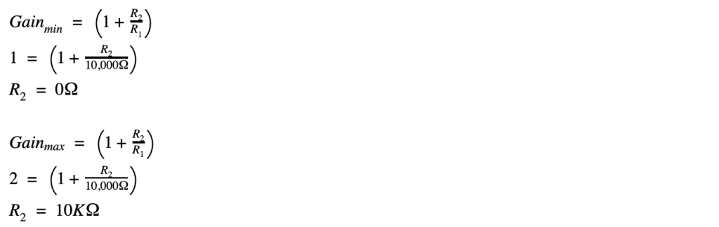
Work for a non-inverting amplifier without a potentiometer:

Work for a non-inverting amplifier with a potentiometer:

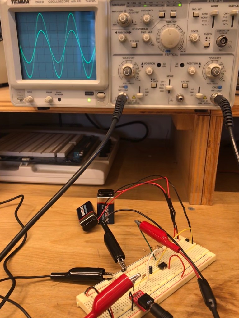
Inverting Amplifier

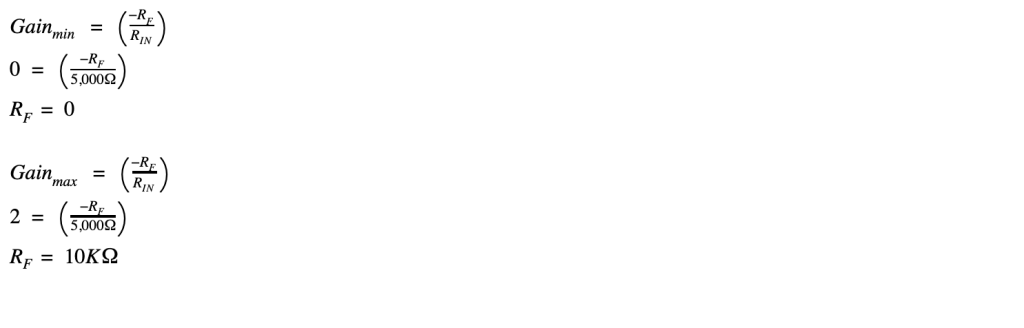
Work for an inverting amplifier without a potentiometer:

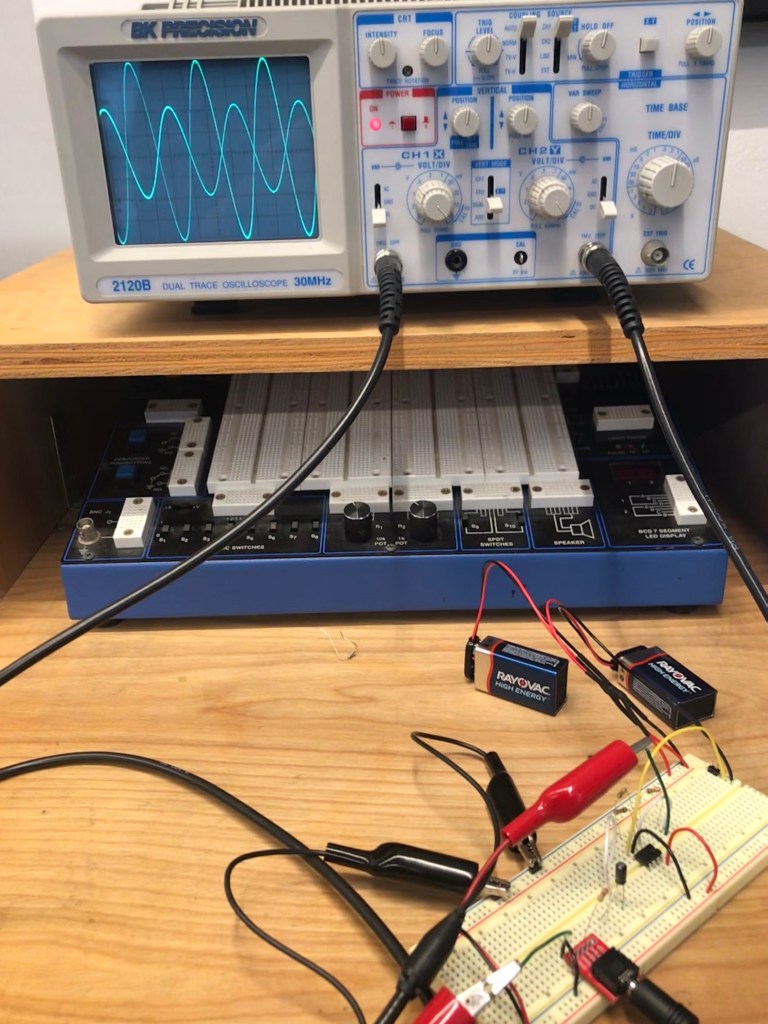
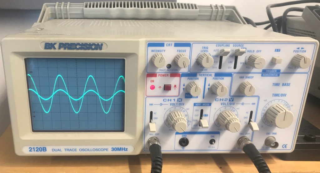
The inverting amplifier changes the output from the op amp (channel 2) to an inversion of the original sine wave (original is channel 1).

Work for an inverting amplifier with a potentiometer:

Photocell

Removing the potentiometer from the inverting amplifier and replacing it with a photocell

Troubleshooting

Troubleshooting notes found HERE

Analog Lab Report 4

February 24, 2020

The Oscilloscope

An oscilloscope graphs Voltage over time. To make it work correctly certain controls must be on. Find the power button and turn it on (it might take a few seconds to fully turn on). Then flip the “vert mode” switch to Ch.1 to only see that channel. Make the under “CH.1” that the Volt/div knob is at .5 and the inner dial is as far clockwise as possible (you will hear a click when it is at the correct position). Set the var switch under channel 1 to ground so that all you see is a horizontal line. This will allow you to easily adjust the vertical height. Using the vertical position knob for channel one, adjust the position so that the line is on the x-axis (if you can’t see the line, check to make sure that the position isn’t turned all the way in one direction or the other). Finally, once you’re done adjusting, switch “Var” from ground to DC. Switch the “Vert Mode” to “CH2” and repeat the same thing for channel 2. Under “Horizontal” turn the “Tine/Div” knob to .5 so that you will be able to see the waveform clearly. Then Make sure the Coupling switch is set to TV-V or Auto. Connect your circuit to channel 1 and channel two and change the “Vert. Mode” to “dual” to see both channels.

Volts/Div and Time/Div

The X and Y axis represent time and voltage respectively. By changing the volts per div the amount of the signal that is seen changes. The volts per div changes the number of volts that are seen in each of the blocks in the grid. The time per div determines how much time each of the little blocks is on the grid (scale of the grid). By changing this you also change how much of the signal you see.

The Trigger Controls

The trigger controls allow you to change what you see. There is a control, “Vert Mode”, to change between seeing ch.1, ch.2, and duel. When adjusting channels individually set this to channel one or two and when looking at the waveforms together, set it to dual. Use the position trigger knob to adjust where the wave is on the screen. You want to have this set in the middle so you are able to see a clear unmoving waveform. And finally, you will use one to set the trigger mode to set it to TV-V or auto so the oscillator can determine how to display the voltage.

More Information

  • Make sure to trace your connections so you are sure you have the correct input on the oscilloscope and know what you’re looking at.
  • Always connect the red probe to the input and the black probe to ground.
  • Make sure your volume is all the way up on your computer (or whatever divide you are using to create the sin wave)

The Potentiometer

When the pot is turned all the way to zero there is zero resistance so the oscillator will show a maximum amplitude of the voltage (Y-axis). This shows up on the oscilloscope as a full waveform. However, as you turn the pot in the opposite direction the resistance increases and the output becomes less and less. This appears as a straight line on the oscilloscope. The minimum amplitude of the output wave as a percentage of the input wave is 0% when the resistance is increased fully and the wave appears as a horizontal line. The maximum amplitude is 100% when there is zero resistance and the output and input waves match.

Videos

Troubleshooting

Troubleshooting notes found HERE

Design a site like this with WordPress.com
Get started